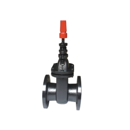
How to Calibrate Gate Valve Actuators and Controls
Introduction
Gate valves are essential components in industrial piping systems, used to control the flow of liquids and gases. Proper calibration of gate valve actuators and control systems ensures efficient operation, prevents leaks, and extends the lifespan of the equipment. This guide provides a detailed, step-by-step approach to calibrating gate valve actuators and controls, covering mechanical, pneumatic, hydraulic, and electric actuators.
---
1. Understanding Gate Valve Actuators
Actuators are devices that automate the opening and closing of gate valves. They can be classified into three main types:
1. Pneumatic Actuators – Use compressed air to operate.
2. Hydraulic Actuators – Use pressurized fluid for movement.
3. Electric Actuators – Use electric motors for operation.
Each type requires specific calibration procedures to ensure accurate positioning and responsiveness.
---
2. Pre-Calibration Preparation
Before calibration, follow these preparatory steps:
2.1 Safety Precautions
- Lock out and tag out (LOTO) the system to prevent accidental operation.
- Depressurize the pipeline if necessary.
- Wear appropriate personal protective equipment (PPE).
2.2 Tools and Equipment
- Multimeter (for electric actuators)
- Pressure gauge (for pneumatic/hydraulic actuators)
- Calibration software (if applicable)
- Torque wrench
- Position indicator
2.3 Inspection
- Check for leaks, corrosion, or mechanical damage.
- Verify electrical connections (for electric actuators).
- Ensure proper air or hydraulic supply (for pneumatic/hydraulic actuators).
---
3. Calibration Procedures
3.1 Pneumatic Actuator Calibration
Pneumatic actuators rely on air pressure to move the valve stem. Calibration involves adjusting the air supply and control signals.
Step 1: Verify Air Supply
- Ensure the air pressure matches the actuator’s specifications (typically 20-100 psi).
- Check for leaks in air lines using a soap solution.
Step 2: Adjust Control Signal
- Connect a pressure gauge to the actuator’s control port.
- Apply a 4-20 mA or 3-15 psi control signal (depending on the system).
- Verify that the valve fully opens at 20 mA (or 15 psi) and fully closes at 4 mA (or 3 psi).
Step 3: Position Feedback Calibration
- Use a positioner to adjust the valve’s travel.
- Ensure the valve reaches 0% (closed) and 100% (open) positions accurately.
Step 4: Test Operation
- Cycle the valve multiple times to confirm smooth movement.
- Check for any sticking or delayed response.
---
3.2 Hydraulic Actuator Calibration
Hydraulic actuators use fluid pressure for operation and require precise pressure adjustments.
Step 1: Check Hydraulic Fluid Level
- Ensure the reservoir has sufficient clean hydraulic fluid.
- Inspect for leaks in hoses and fittings.
Step 2: Adjust Pressure Settings
- Connect a pressure gauge to the hydraulic supply line.
- Adjust the relief valve to the required operating pressure.
Step 3: Calibrate Position Feedback
- Use a linear variable differential transformer (LVDT) or potentiometer to verify valve position.
- Adjust feedback sensors to match the valve’s travel.
Step 4: Test and Verify
- Cycle the valve and observe smooth operation.
- Check for excessive noise or vibration, which may indicate misalignment.
---
3.3 Electric Actuator Calibration
Electric actuators use motors and gear mechanisms to operate the valve.
Step 1: Electrical Checks
- Verify voltage and current supply match the actuator’s rating.
- Check wiring for loose connections or damage.
Step 2: Torque Adjustment
- Set the torque limit to prevent overloading the motor.
- Use a torque wrench to verify the actuator’s torque setting.
Step 3: Position Calibration
- Use a position indicator to set open/close limits.
- Adjust limit switches to ensure the valve stops at the correct positions.
Step 4: Test Operation
- Run the actuator through multiple cycles.
- Monitor for overheating or unusual noises.
---
4. Control System Integration
Modern gate valves often integrate with PLCs (Programmable Logic Controllers) or DCS (Distributed Control Systems).
4.1 Signal Calibration
- Ensure the control signal (4-20 mA, 0-10 V, or digital signals) matches the actuator’s input range.
- Use a signal generator to simulate control inputs and verify response.
4.2 Feedback Loop Adjustment
- Configure the control system to receive position feedback from the actuator.
- Adjust PID (Proportional-Integral-Derivative) settings for smooth operation.
4.3 HMI (Human-Machine Interface) Verification
- Check that the valve status (open/closed) is accurately displayed on the HMI.
- Test emergency shutdown functions if applicable.
---
5. Post-Calibration Testing
After calibration, perform the following tests:
5.1 Leak Test
- Pressurize the system and inspect for leaks at the valve stem and connections.
5.2 Full Stroke Test
- Cycle the valve from fully open to fully closed multiple times.
- Verify consistent performance without sticking or delays.
5.3 Emergency Shutdown Test
- Simulate an emergency stop to ensure the valve closes as expected.
---
6. Maintenance and Troubleshooting
6.1 Common Issues
- Valve Sticking – May indicate misalignment or insufficient lubrication.
- Slow Response – Check air/hydraulic supply or electrical connections.
- Position Drift – Recalibrate feedback sensors.
6.2 Preventive Maintenance
- Lubricate moving parts regularly.
- Inspect seals and gaskets for wear.
- Monitor actuator performance trends.
---
Conclusion
Proper calibration of gate valve actuators and controls ensures reliable operation, reduces downtime, and enhances safety. By following structured calibration procedures for pneumatic, hydraulic, and electric actuators, operators can maintain optimal performance in industrial applications. Regular maintenance and testing further extend the lifespan of the equipment, ensuring long-term efficiency.
By adhering to these guidelines, engineers and technicians can achieve precise valve control, minimizing operational risks and maximizing system reliability.
This website uses cookies to ensure you get the best experience on our website.
Comment
(0)